Wet filtration at full scale
The wet filtration test campaign had proven the approach. A water-washed media wall could pull calcium dust out of fast airflow with far less maintenance than cloth filters. That earned the green light: a full-sized unit, integrated into the carbonation prototype skid, with the details to be worked out in operation. One person, one month. Design it, procure it, build it, test it, as fast as possible.
The other problem I saw coming but could only lessen was now here. The skid was already tightly designed, and the wet filtration had to fit into what was left. We had elected to use pallet racking as the prototype skid as it was very fast to set up, supported weight well, and could be configured to our requirements. It also came with a fixed length, so my filter depth was locked in at about half the depth the test campaign suggested would do the job best. I modeled the unit in Onshape, fitting it to the existing model. For the first time, my work was designed parametrically into the rest of the team's.
The design
Water gets pumped from a tank up to spiral spray nozzles above the media wall, cascades down through the media where it catches the calcium dust, drains back, and goes around again. A filter manifold cleans the recirculating water, and a solenoid on a timer dumps the captured slurry to a slop tank so the filters don't have to hold everything.
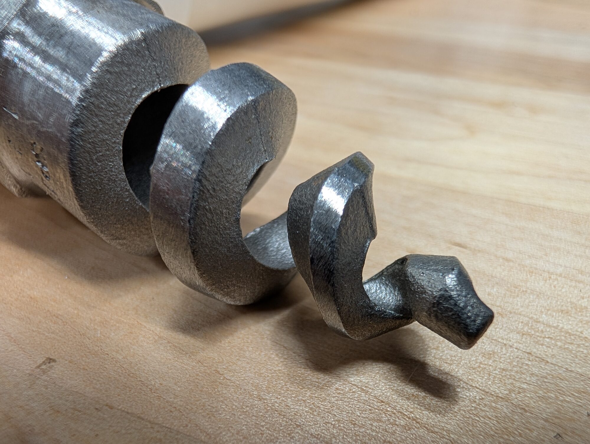
A spiral nozzle — the whole spray pattern comes from one machined helix, no moving parts and not much to clog. This worked better than other solutions I tested but to work in such a tight space it would need the spiral nozzles to spin for full and fairly uniform coverage of the filter media.
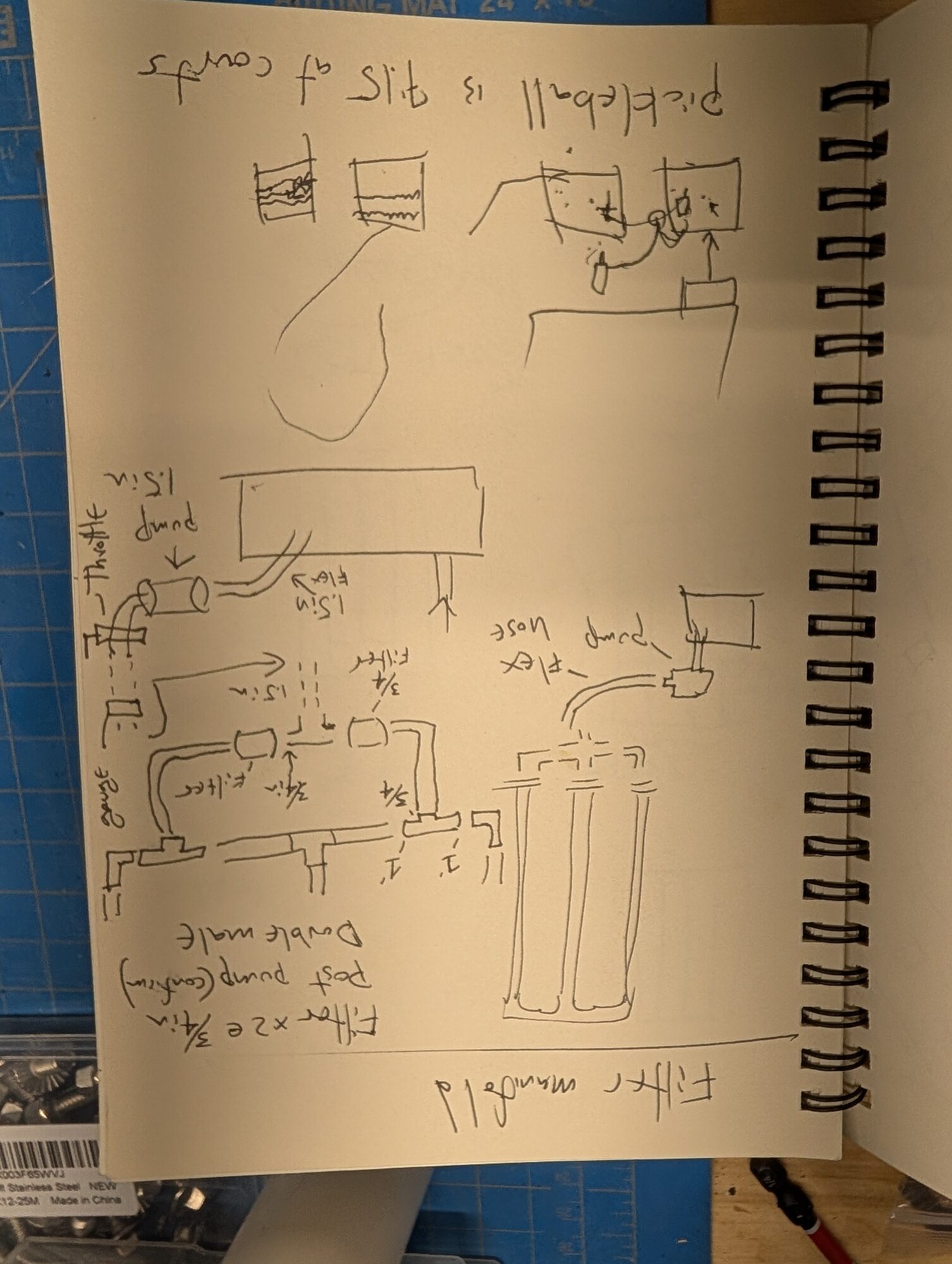
The first pass on paper. Filter manifold — two 3/4″ filters, post-pump, 1.5″ pump plumbing, throttle and gauge.
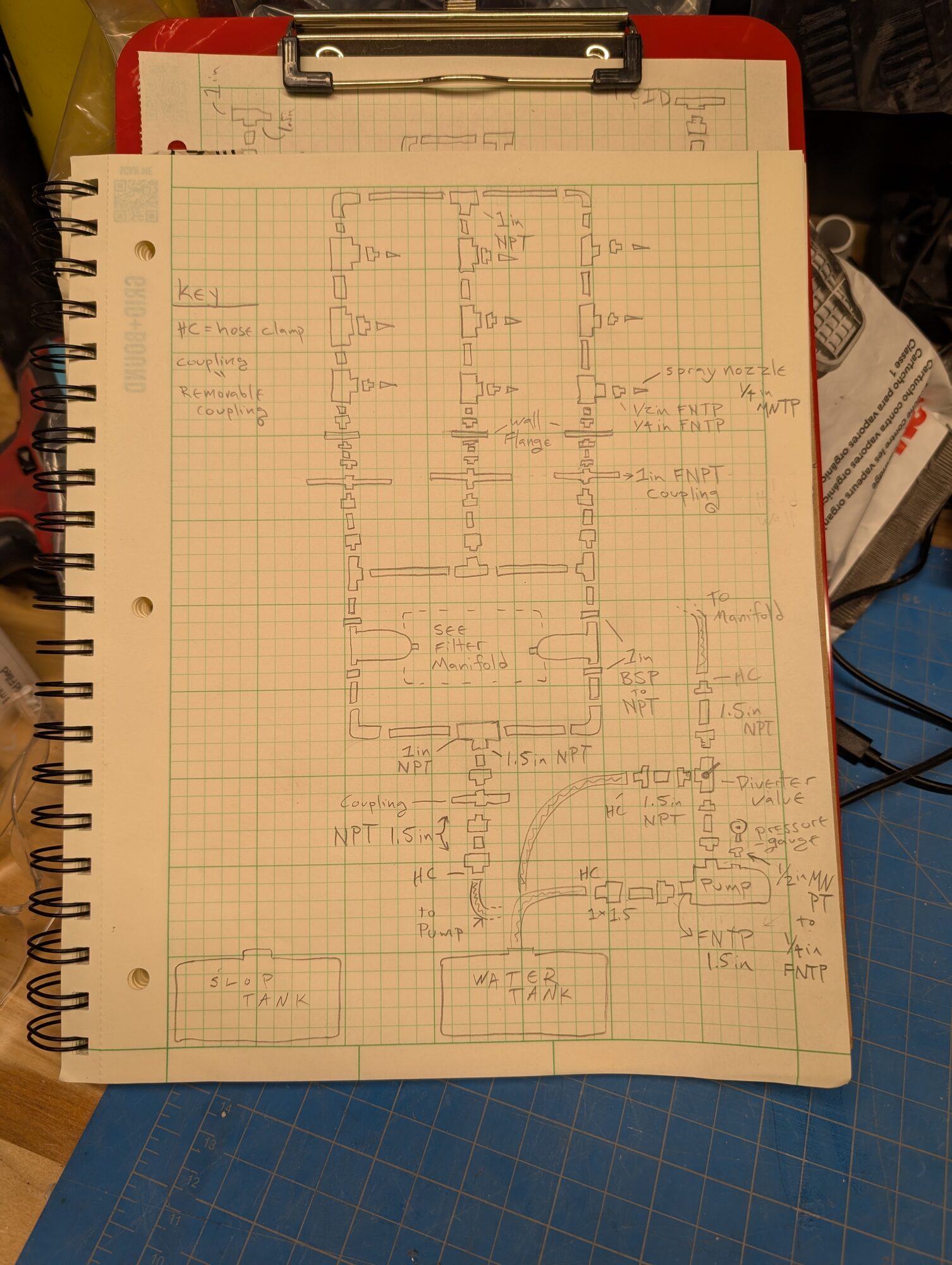
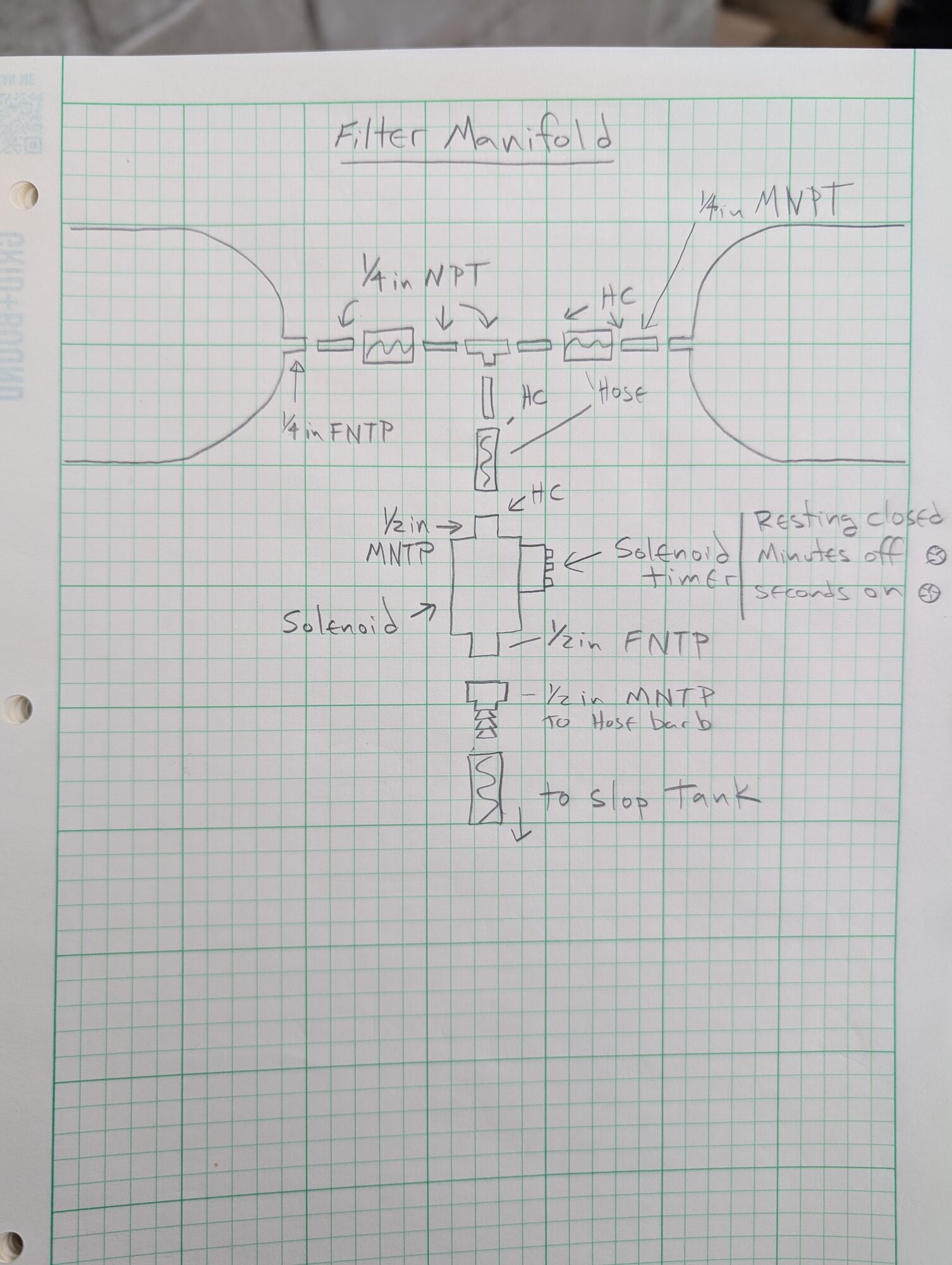
The system on grid paper. Left: the whole loop — nozzle rows up top, filter manifold, diverter valve, pressure gauge, pump, and the water tank and slop tank at the bottom. Right: the filter manifold and the timed solenoid — resting closed, minutes off, seconds on — that purges to the slop tank.
Procurement, and the surplus shelf
All of the stainless formed parts were sourced through Fabworks (like SendCutSend but they'll work with slightly larger parts). In the hurry to get it all done and sent to cut I used their webform wrongly, and thereby ended up with two parts that were identical rather than mirrored. I called immediately and managed to turn it into a much tighter relationship with Fabworks with single day turnaround now offered to us as needed.
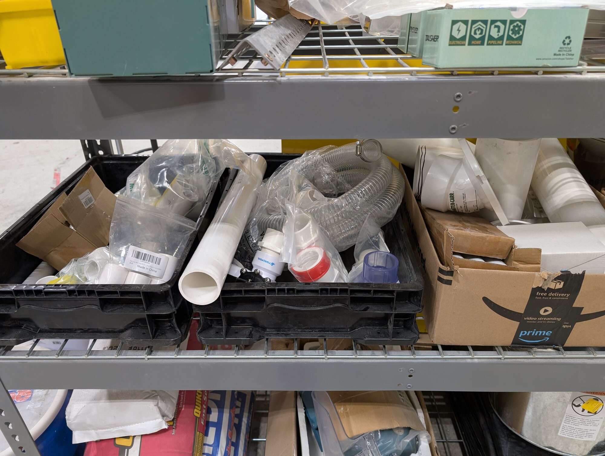
The surplus shelf pulling its weight again.
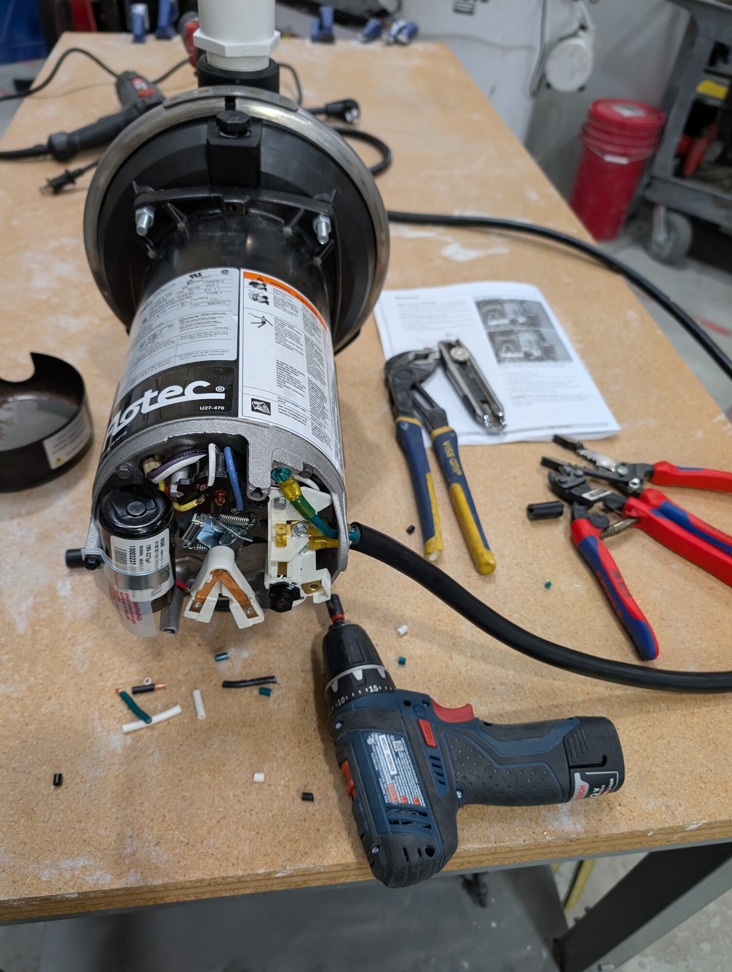
Into the pump before it ever ran. Safety compliance was critical at Terraform so I got to have my electrical rewiring critiqued by our senior electrical engineer and learned some great tricks in the process
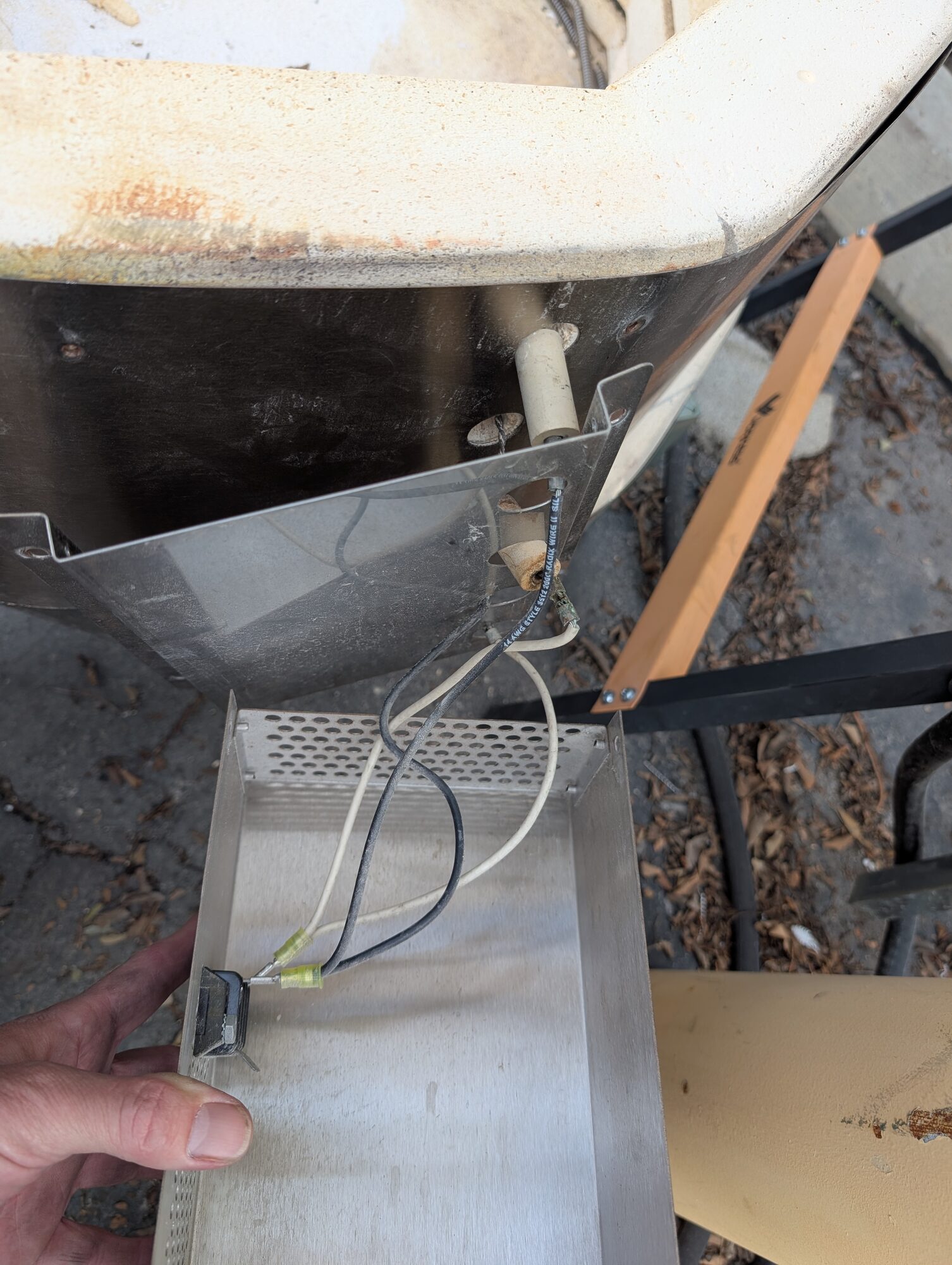
There are always side quests. This one was to repair one of our kilns, I find that sometimes a little bit of off project work can keep the mind limber
Building the manifold
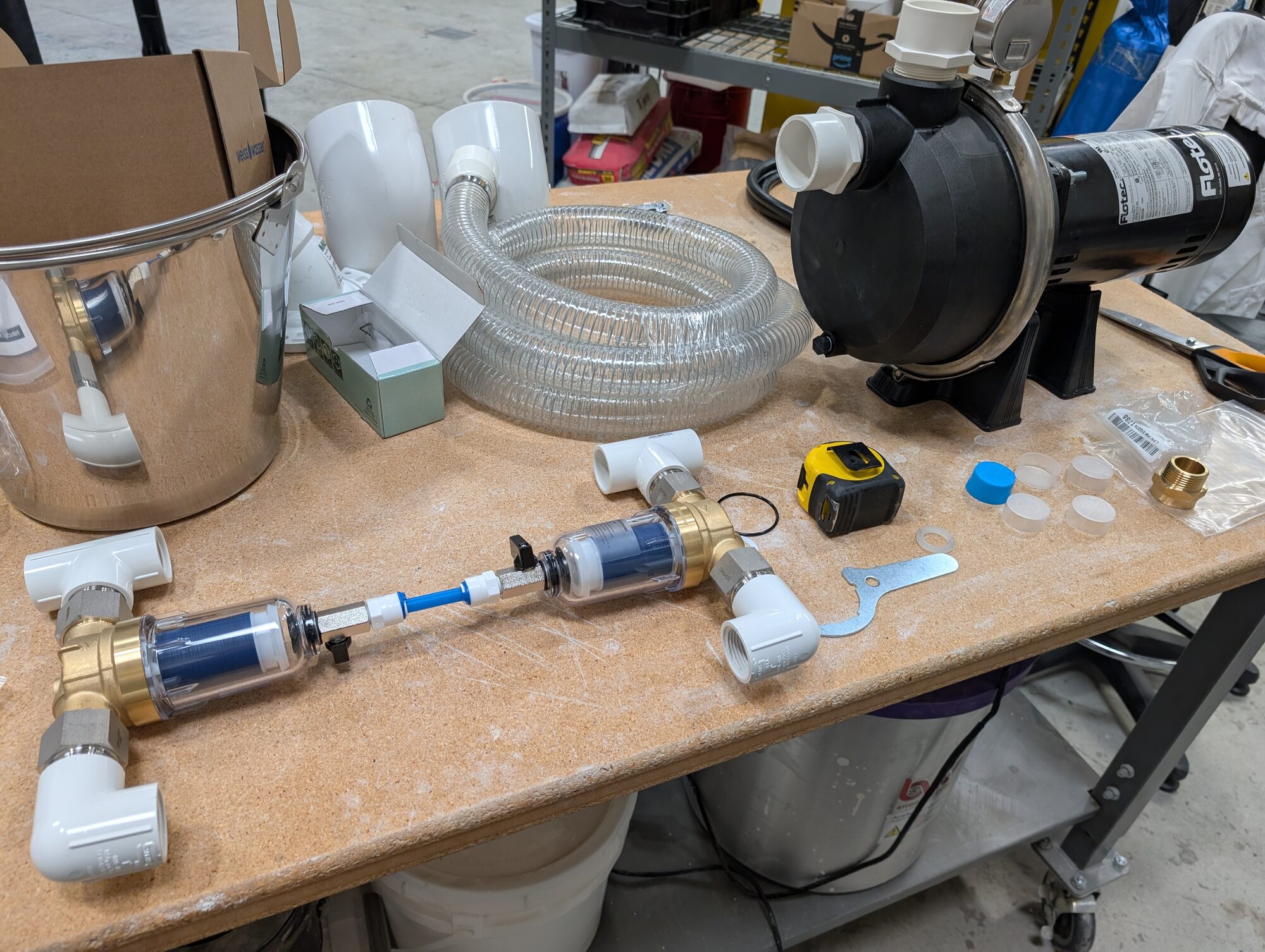
First fit-up on the bench — the two filter housings meeting their unions, the pump waiting its turn. Everything seems to get a little more complicated when done quickly
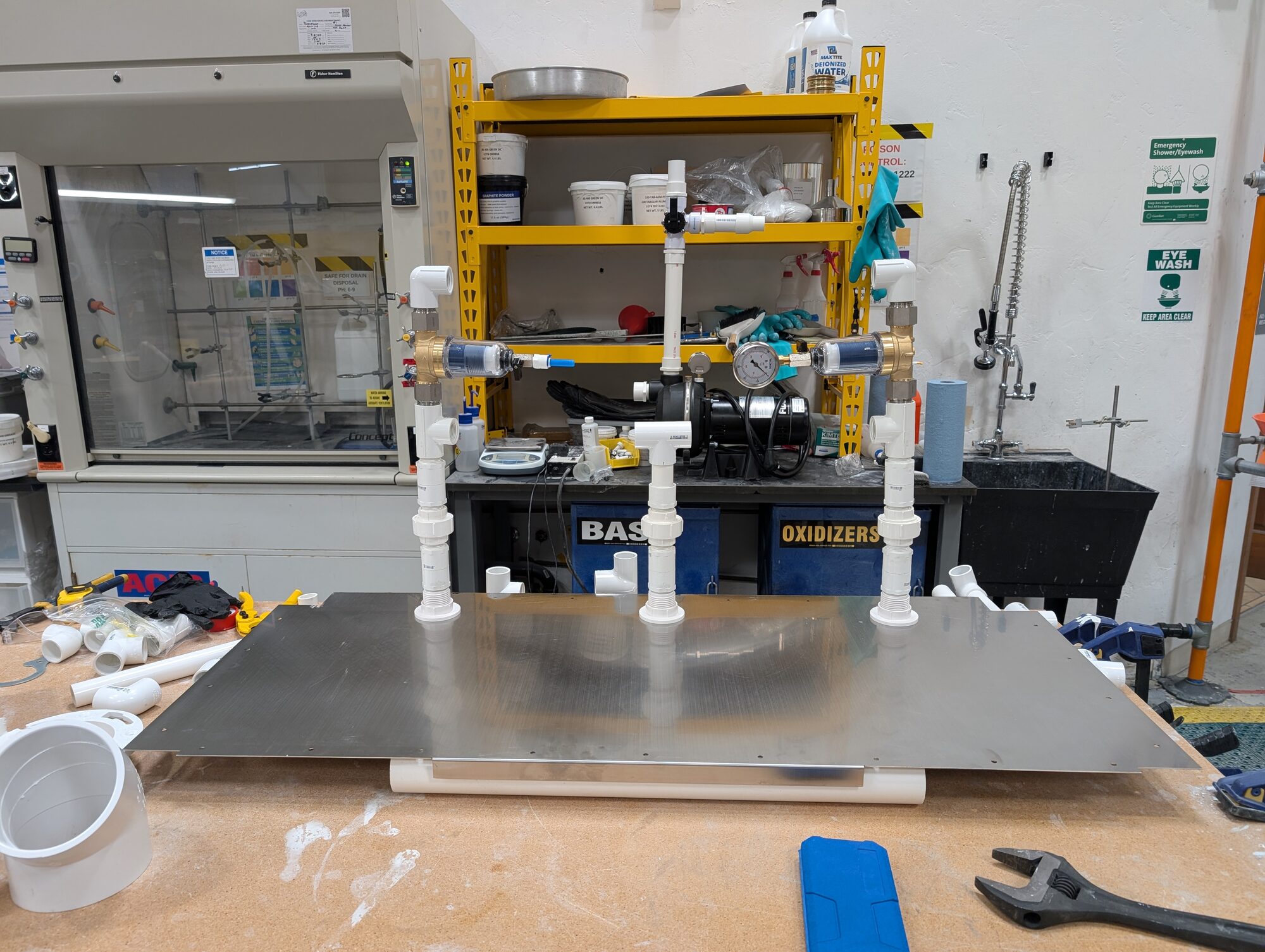
Dry fit in the lab. The manifold mounts to a stainless sheet so the whole water system comes off the skid as one piece. The twinned filter manifold lets them purge on alternating cycles.
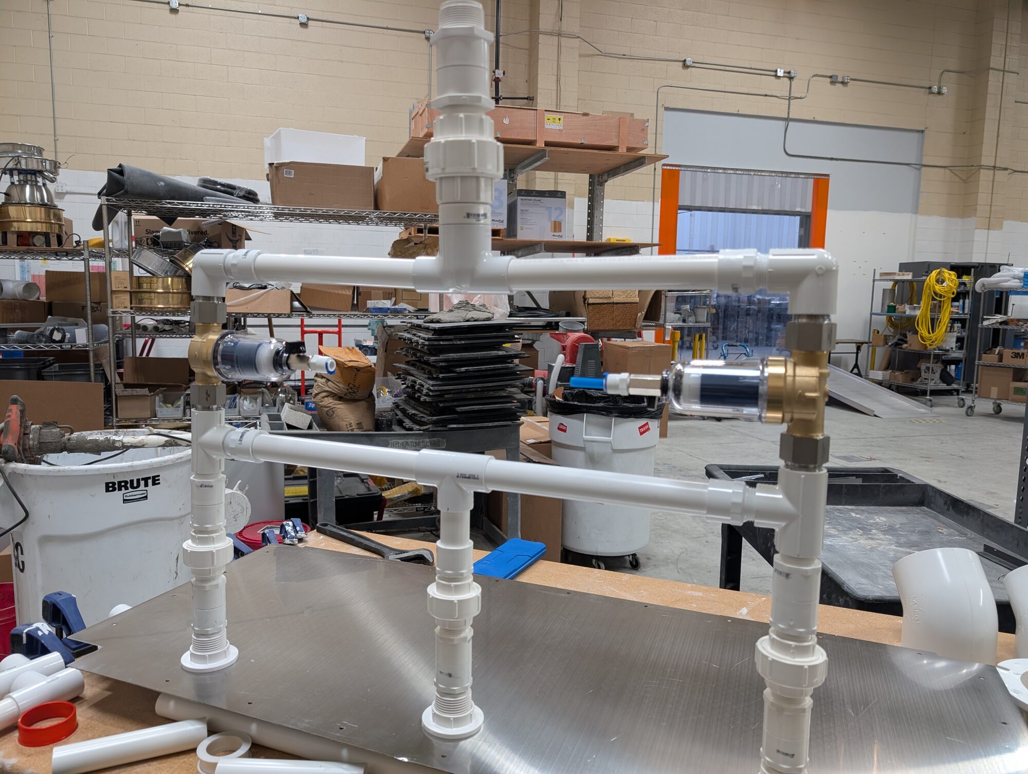
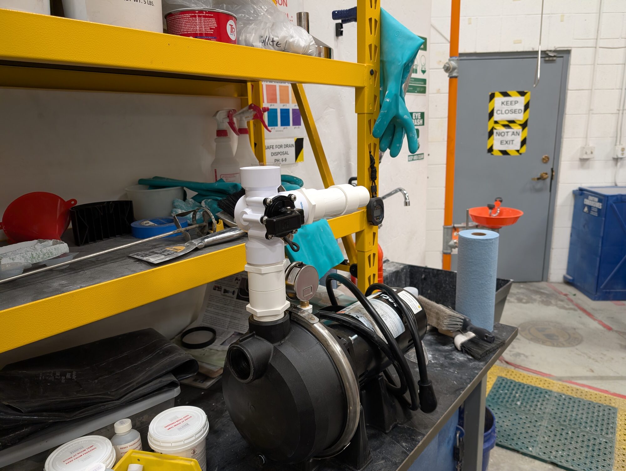
Left: the manifold taking its final two-tier shape — unions at every joint so any run can come out without cutting. Right: the pump discharge coming together.
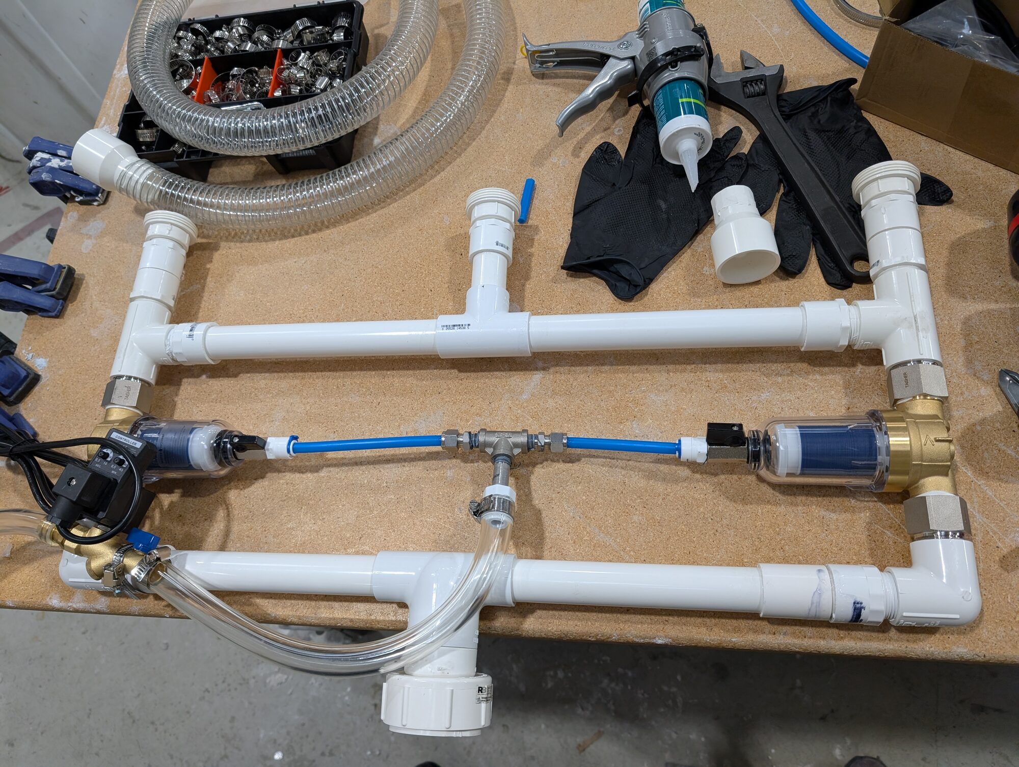
Complete on the bench: filters, solenoid, and the sense line to the gauge. Hose clamp bins at the ready.
Fitting it into the skid
This is where the tight tolerances expressed in the body of the wet filter device. The skid had settled and the rest of the prototype moved 2mm between design and install. Fortunately the seating tabs were designed with that possibility in mind and so 5 minutes with a cutting wheel worked it out.
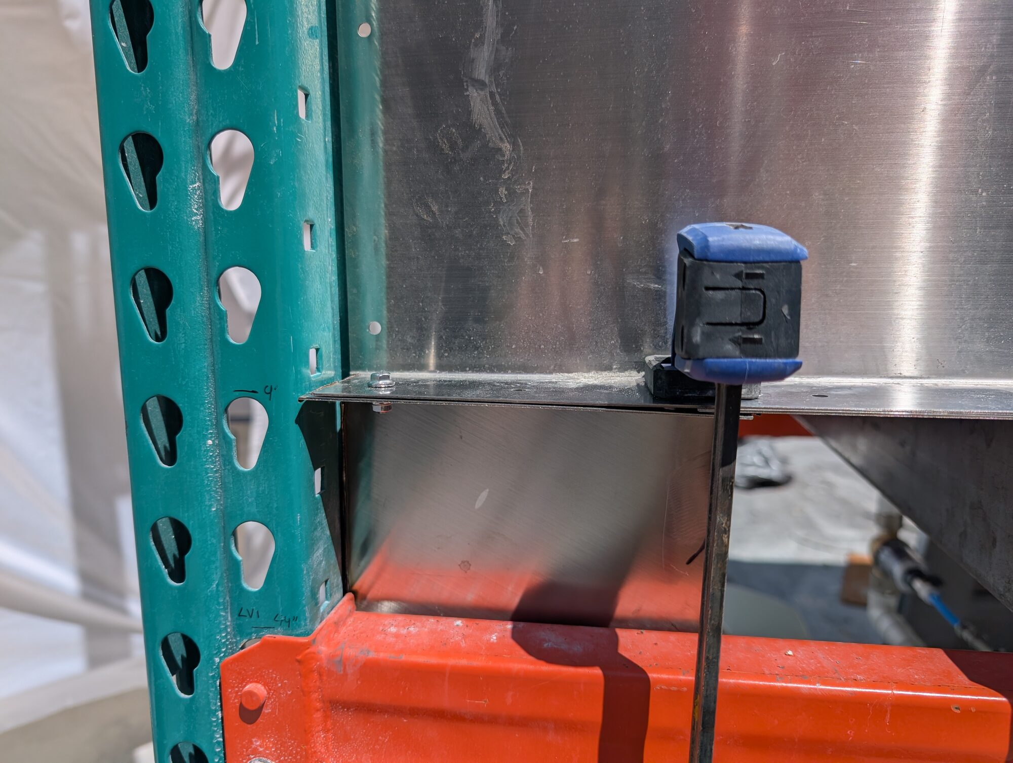
Measuring the mounting bracket against the racking. I was honestly thrilled with the fitup. Fast build with tight tolerances can be like juggling eggs.
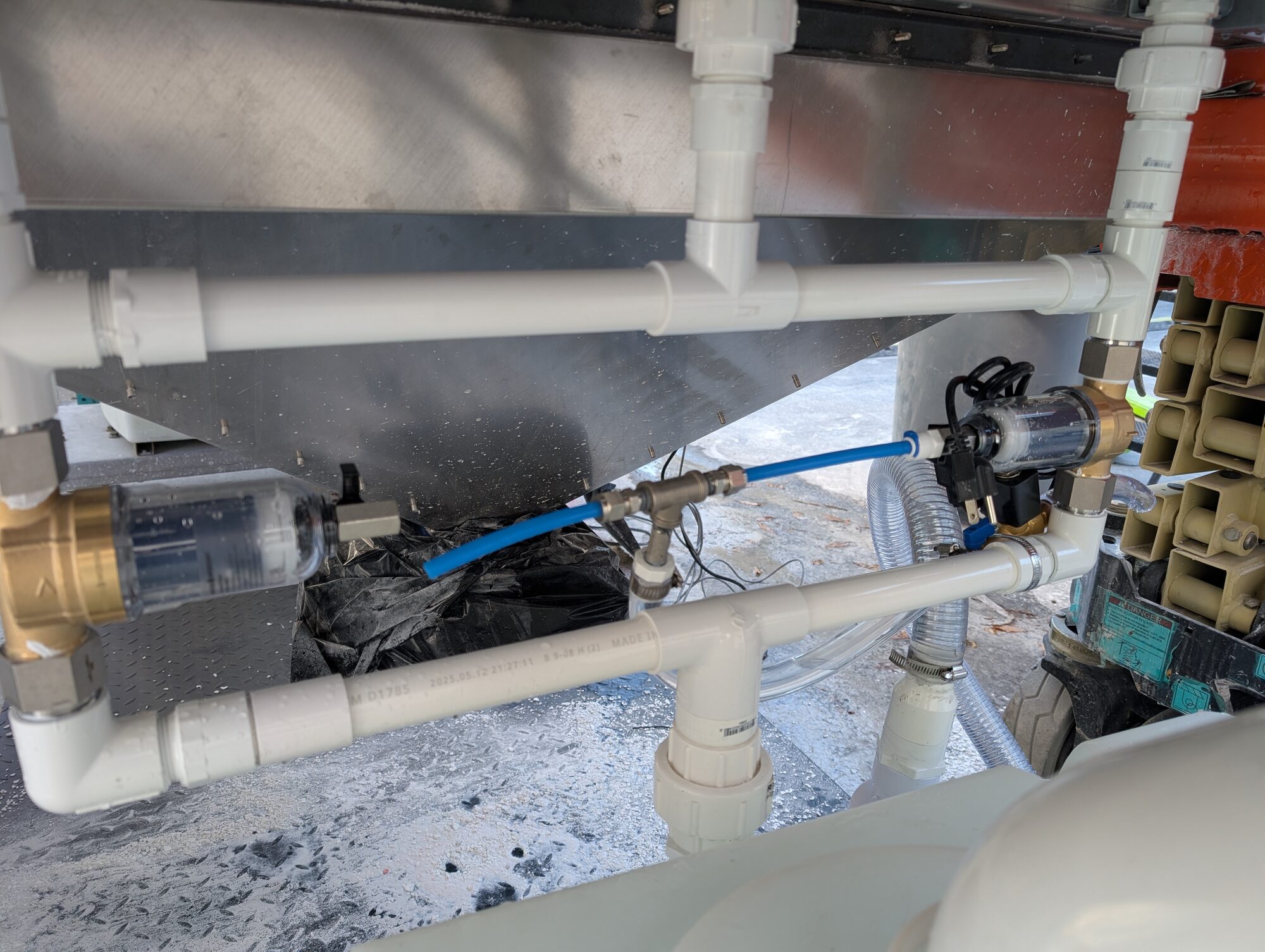
Installed. The manifold lives in the space under the hopper — the space nobody else wanted.
First water
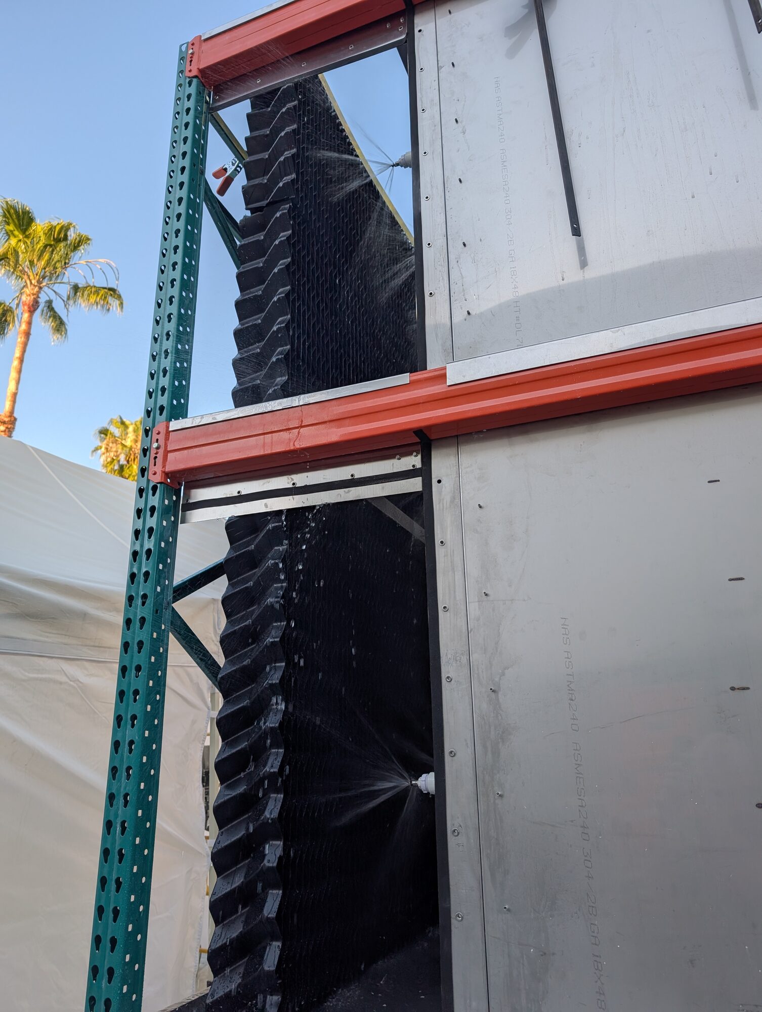
Nozzles on. The spiral pattern covers the media wall top to bottom. Test as you build!
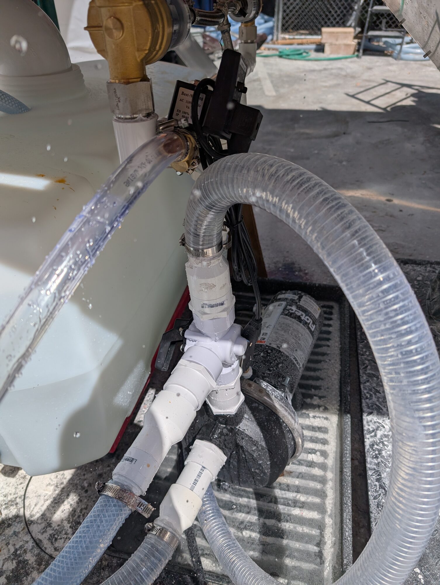
First water through the loop. Not always the prettiest, but we're here to win science this time.
The wall running — water cascading the full height of the media, the tank and pump tucked in below. This was the 'sigh of relief' moment, fit up and functional test complete.
Did it work?
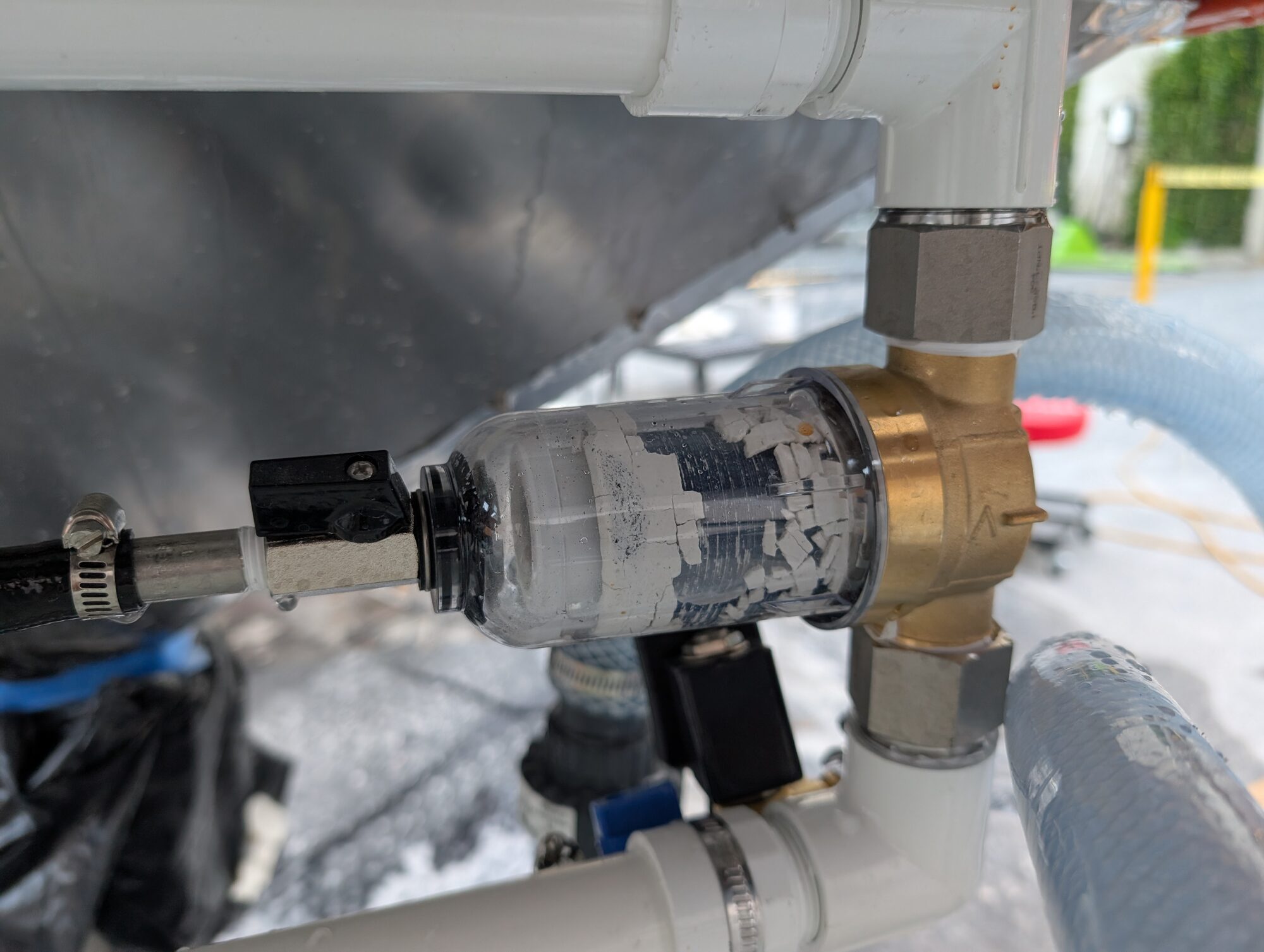
The filter bowl answering the question. That white is captured calcium that is not in the air, and not in a cloth filter that needs changing every day.
The filter now in testing with the carbonation device and it clearly worked, for test at least, not final use. However, since time was saved on the flake loading by not classifying it(removing dust and small bits), there was lots of calcium accumulating in the filter discs. As this was a short term problem, we elected to run the unit without filters. While this worked because of the broad orifice spiral nozzle heads, it did cause the holding tank to become overly alkaline fast.
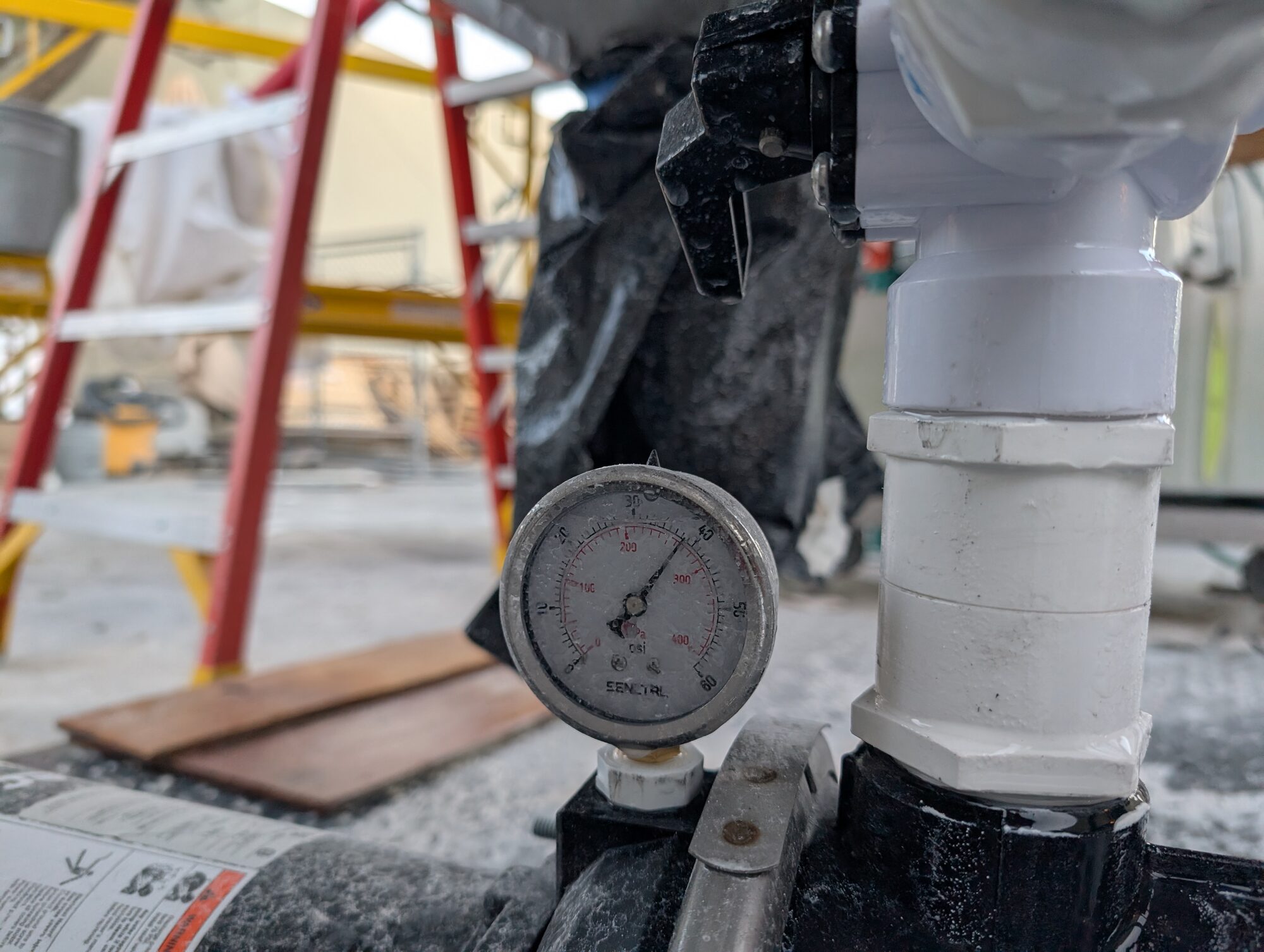
This gauge was primary feedback on clogs in the system, it also gave us good data on nozzle resistance.
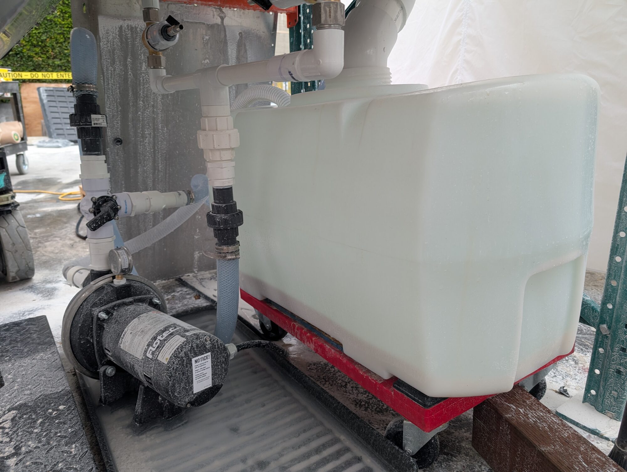
The tank and pump in their working positions. Everything rolls. Make your prototypes nimble!
What went wrong
-
Files to Fabworks. Cost some money and some time working the files wrong in their interface. Lesson: Slow down for web interfaces and file management with vendors. The improved vendor relationship was likely more valuable than the lost time and money, turning 2-3 day rush into 'next day' was a huge win.
-
Management communication. Communication with the technical director was largely handled by the lead engineer on the larger project. Somewhere in that loop there was the expectation that it would be entirely functional without a tuning pass. Lesson: Expect tuning to be needed for all prototypes of new technology.
-
Alkalinity overload The holding tank ended up at around pH 13.5, high enough that hazmat was now needed for all fluid operations. I would have preferred filtering the incoming material to avoid but sometimes we accept the decisions of others and try to minimize the consequences.
What went right
- The test campaign paid off. The full-size unit worked as expected. Improvements needed to be made but a solid working prototype in the first pass at it felt nice.
- Unions everywhere. Rapid prototype plumbing, first time for me, taught me that you want removable couplings -everywhere-.
- Modeled tight, built once. A bunch of tricks in tollerance handling around the thru holes, predicting direction shift, planning hole and bolt connection points to be accomidating, etc., those kept the needed modifications minor.
Role
Solo project: I designed it, procured it, built it, and tested it.
Notes
- Timeline: Design, procurement, build and test were all completed solo in the month of April, 2026.
- Outcome: Functional prototype proven. Iteration ready.