Wet filtration test campaign
Something said at a TF morning meeting stuck with me — about seeing around the next corner. The unseen challenge may impact current decisions, it may also take time to solve, and may thereby be worth looking at sooner rather than later.
The engineers and I were wrapping up the DFM prototype carbonation device. In its current design the calcium dust blown off the flakes we loaded the carbonator with was being captured with cloth filters. We were also preparing to deploy the entire device to the test site, some two hours drive away. Those dust filters would need changing at least daily. Not particularly feasible, and certainly not a long term plan — but also a problem that wasn't going anywhere. What would this device look like in full production? What systems would hold up, and which would become thorns? One of the key goals of prototyping that gets less attention, the designers and operators get lived experience, and key insights that CAD models and whiteboard sessions can easily miss or underrate.
I pondered this and did some research. Compact fast air flow wet filtration for industrial use was viable but not well documented. At our next DAC team meeting I suggested a test campaign to compare solutions, with data. It was approved and I was tasked with writing up a test plan proposal.
The proposal
I proposed one modular test skid that could be reconfigured between wet and dry filtration. Hypothesis: high speed airflow can be de-dusted using low resistance (low ΔP) water coated material, given sufficient air flow interruption.
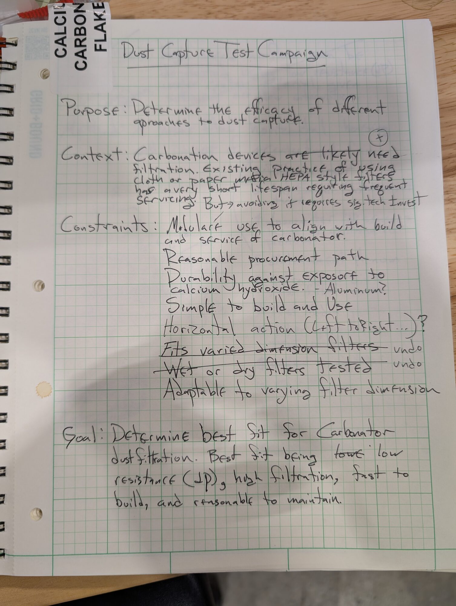
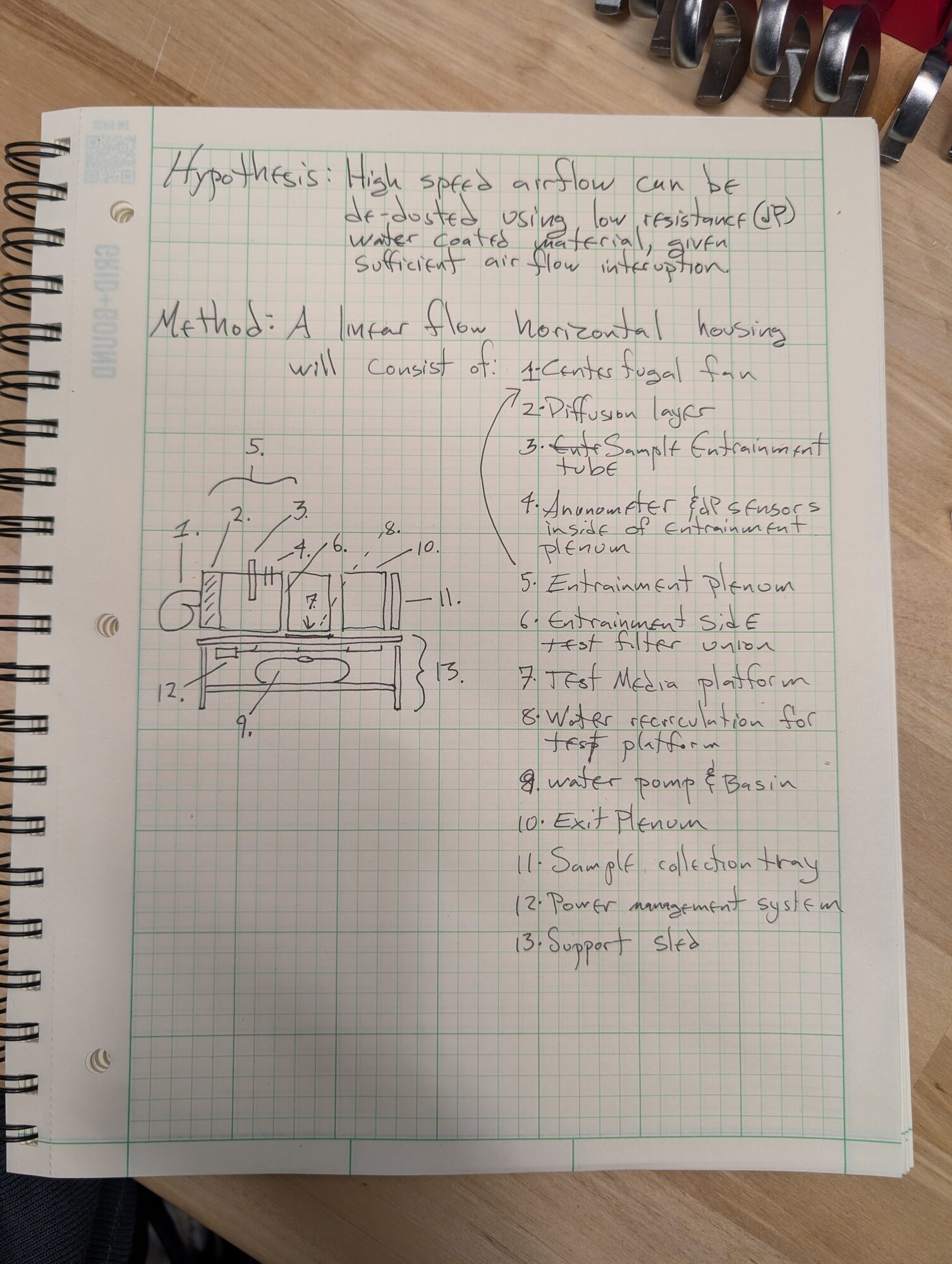
The proposal on paper. Left: purpose, context, constraints, goal. Right: the hypothesis and the method, with the housing sketched out and its parts numbered.
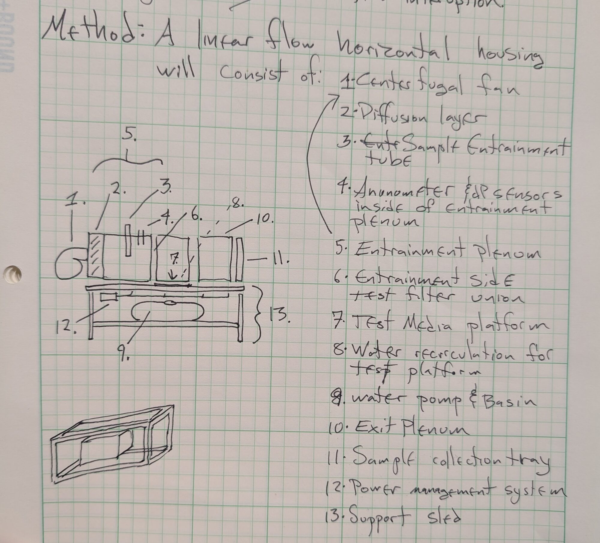
The sketch up close — thirteen parts, and an end view of a cube. The diagram below is this drawing, redrawn as built.
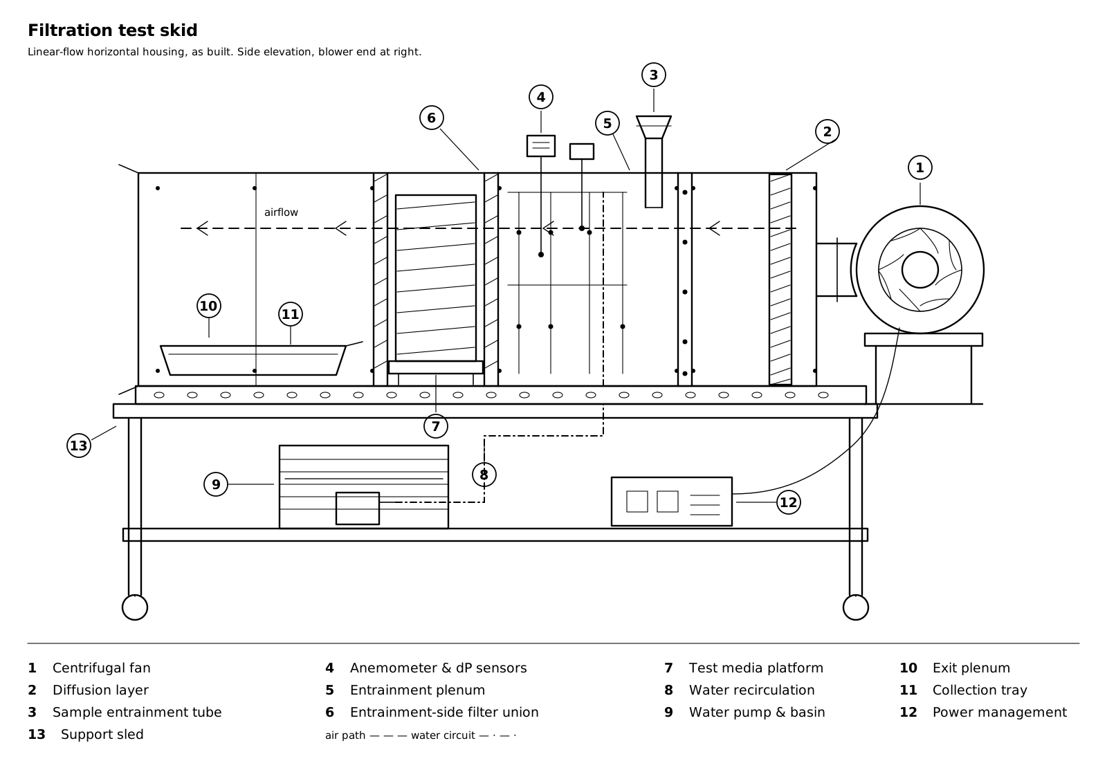
The skid as built. Airflow runs right to left: blower, diffusion layer, then the entrainment plenum where the sample is dropped and the sensors sit, then the test media between its two foam-gasketed unions, then the exit plenum.
Building it
For maximum modularity and flexibility I elected to design as follows:
- Four 10 foot lengths of 2 inch punch stock made a rail mount system atop a wheeled steel table. Don't build what you don't need to.
- Fourteen 2'×2' aluminum sheets, with angle punch stock and nutserts, made three joining cubes on the rail.
- Water held in a tote sat below on a shelf.
- Fan with plywood mount sat on the rail in front of the cubes, joining them.
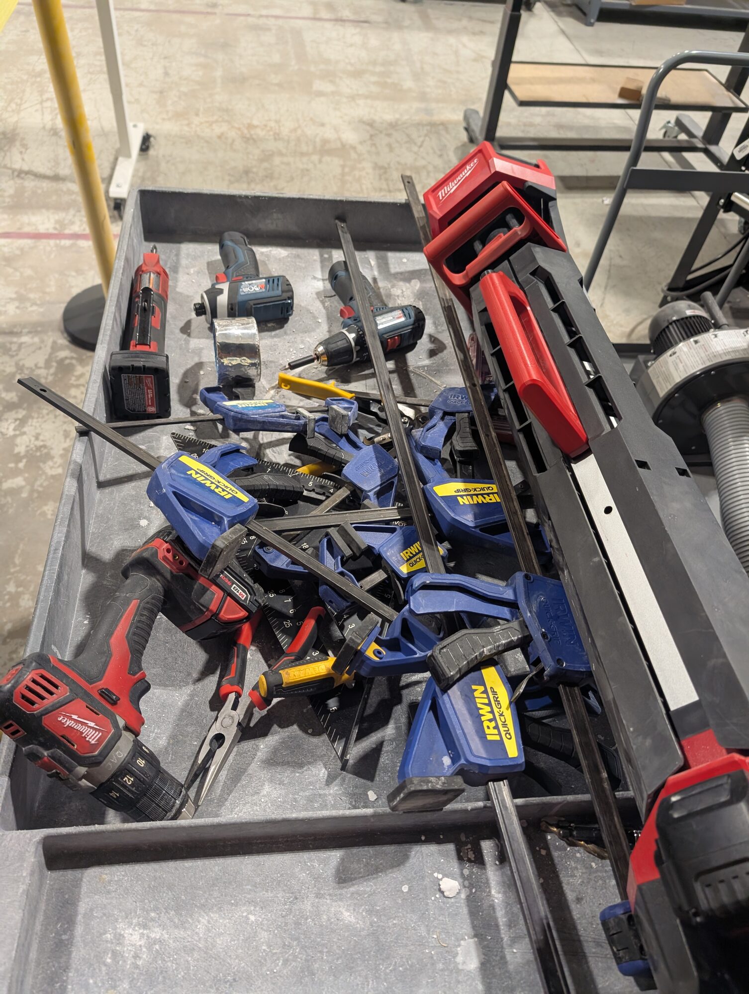
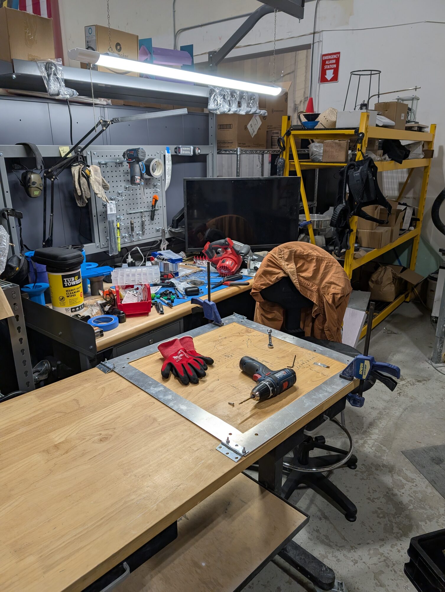
Left: the stock and the clamps this was made of. Right: a cube face coming together on the bench — angle stock around the edge, nutserts going in.
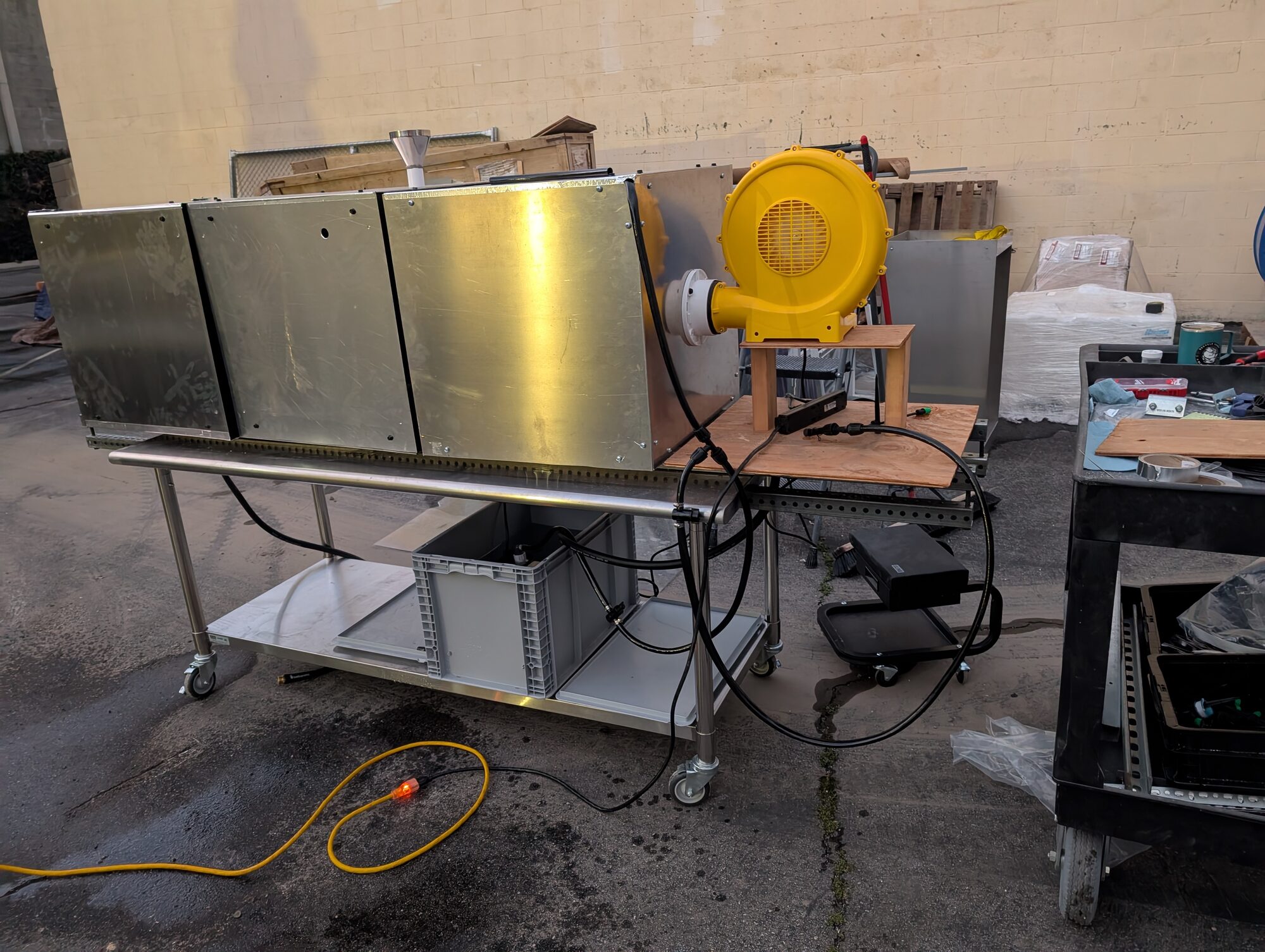
Everything on one rail. 10ft by 2ft
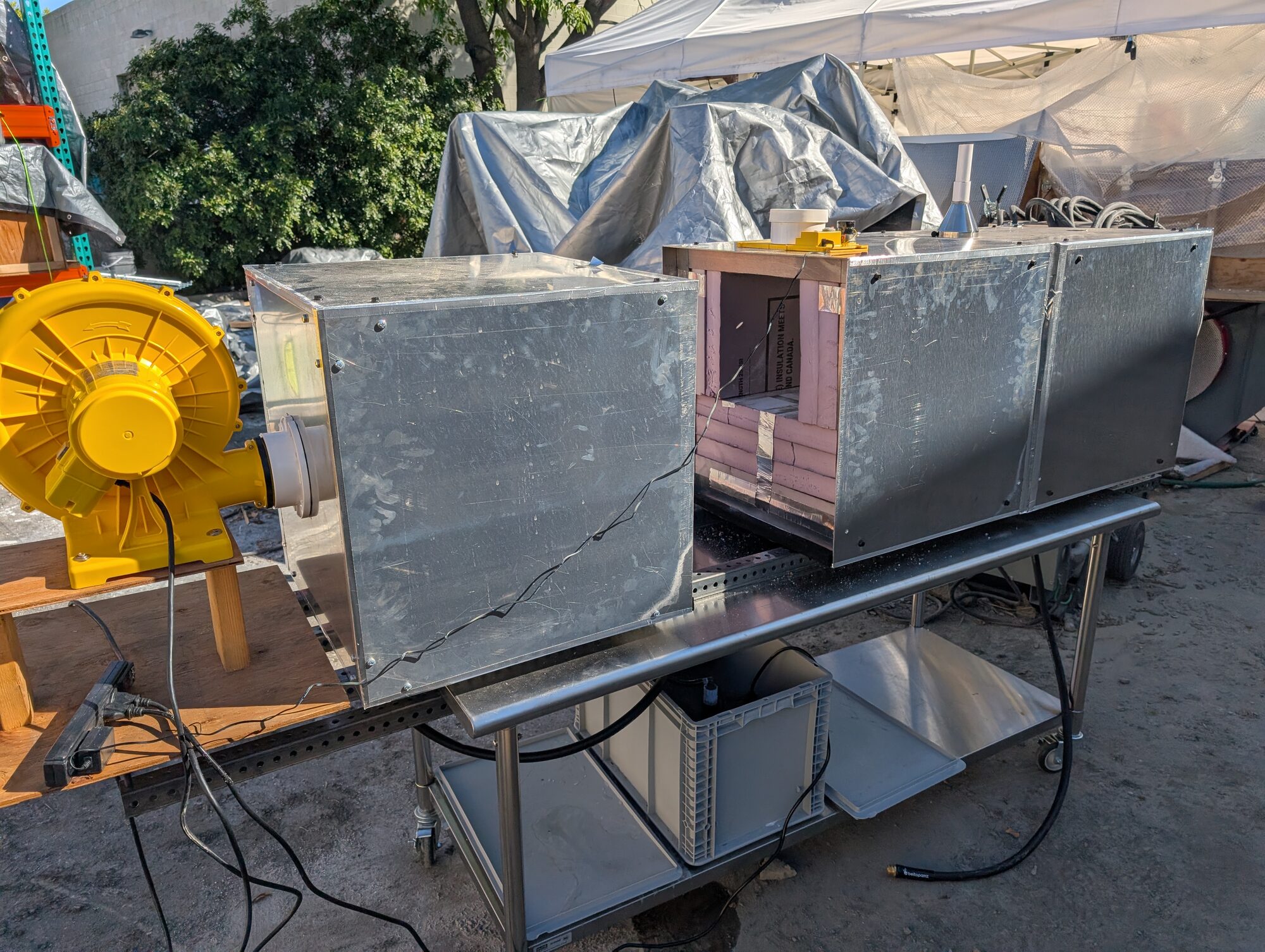
Fan on its plywood mount at the head of the rail, holding the cubes together. The test section is open here with the media frame lifted out.
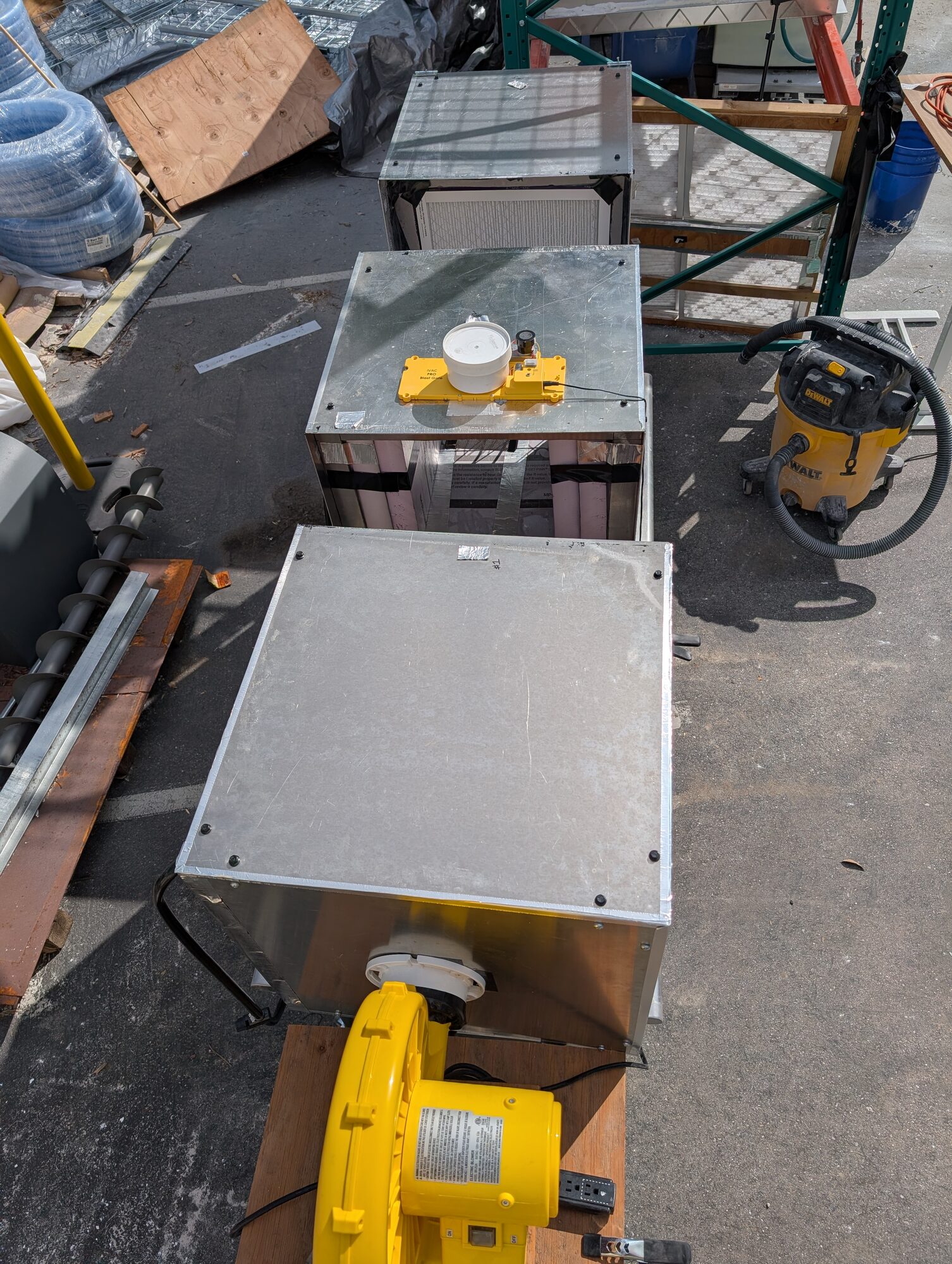
From above, the layout reads at a glance: fan, then three cubes in a line, with the sample gate sitting on the middle one.
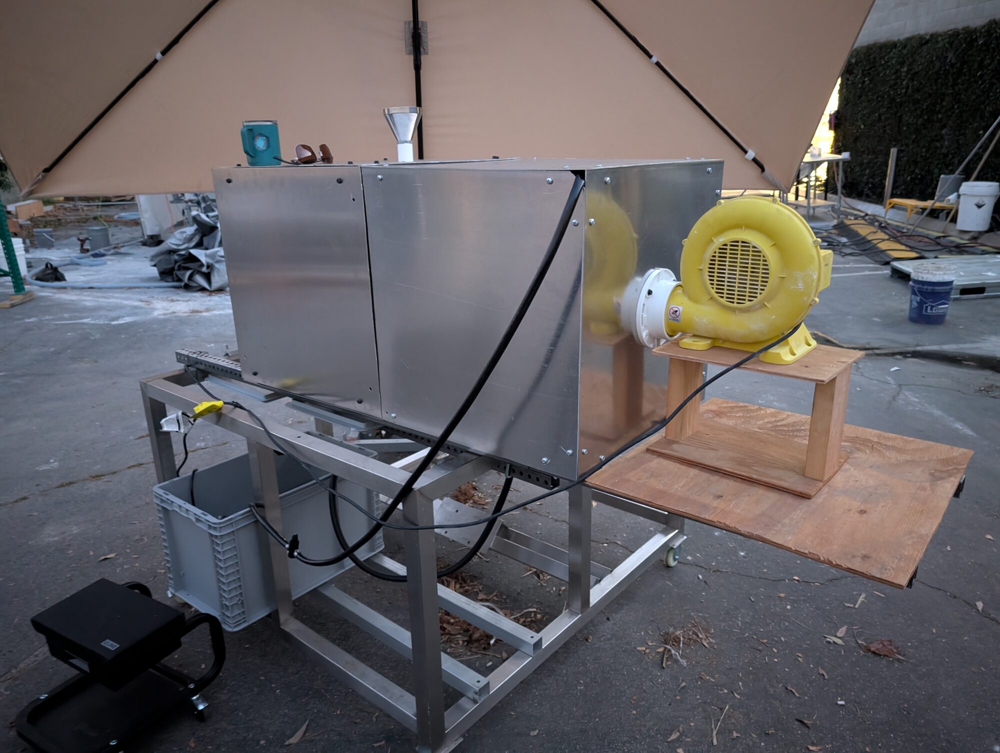
Set up outside under a canopy. The tote and the pump live on the shelf under the table, out of the way of the rail.
The rail let the cubes slide apart for a media change and clamp back together without re-shimming anything.
Getting the sample into the air
The first main challenge ended up being getting the calcium dust samples properly suspended in the air stream. First fix was to reduce airway size where the sample would be dropped, temporarily increasing the air speed. It helped, didn't fix.
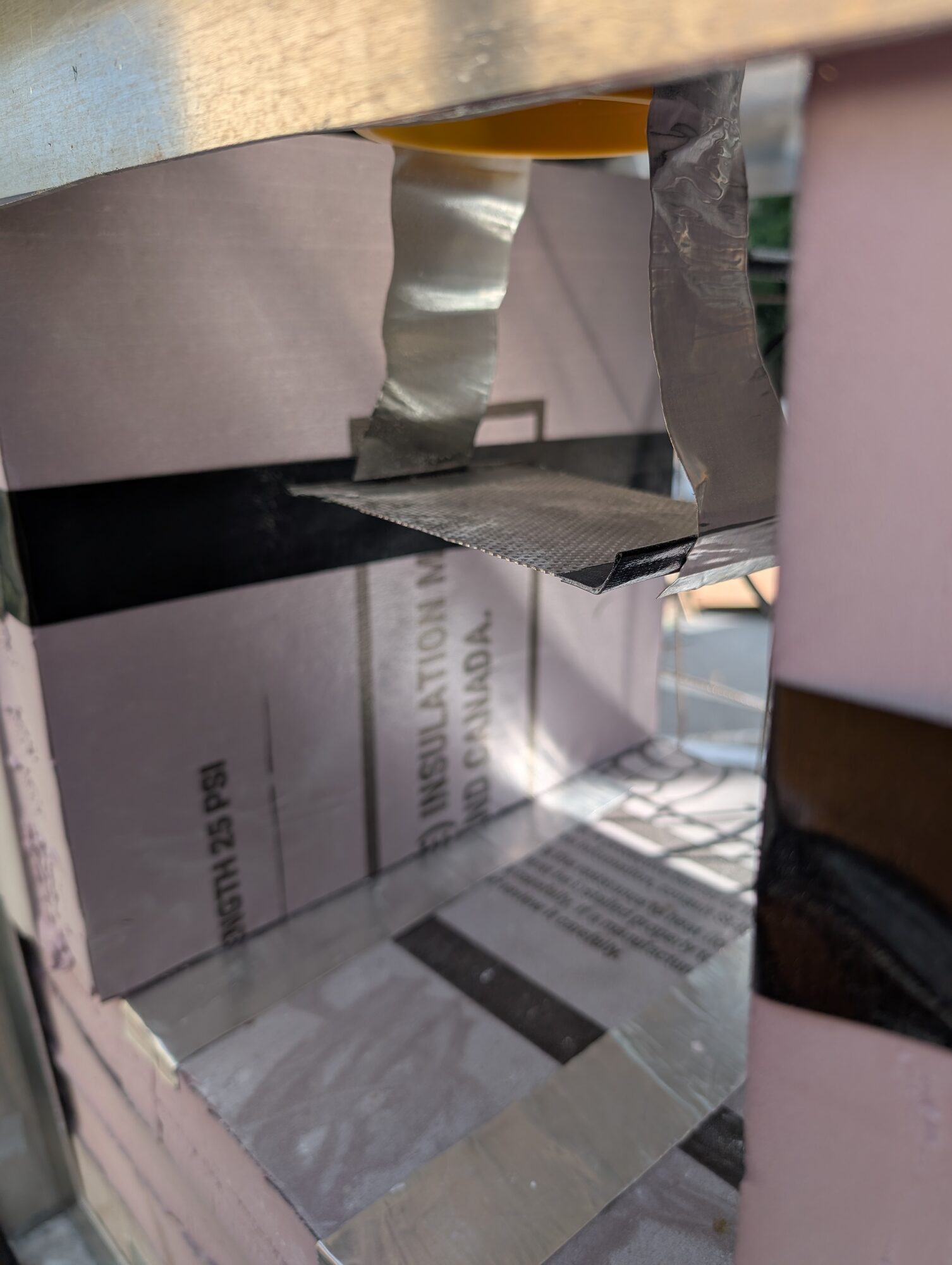
The narrowed airway, looking in from the open face. Sheet metal and foil tape, straight under the drop point.
I ended up using an electronic sanitary gate that was on one of our surplus shelves. The gate provided that if I used measured samples they would be entrained in the airstream consistently, critical for good data.
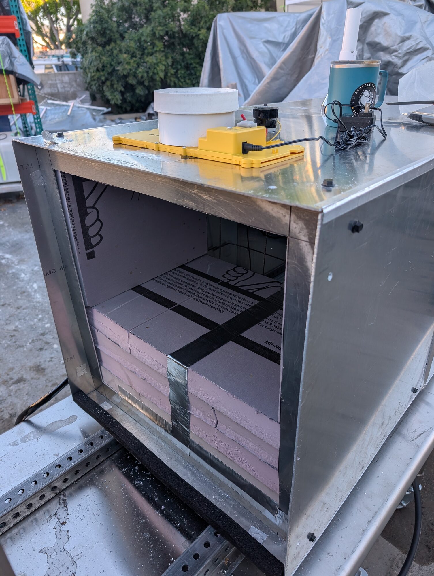
[?: is the yellow box the sanitary gate, and the white cup the measured-sample holder? Read off the photo.] Below it, the test section packed out with XPS foam.
While installing the sample intake it occurred to me that I could use a sling to catch the sample in the center of the airstream. With this method 90%+ of the sample was entrained, which was sufficient, and consistent.
Instrumentation
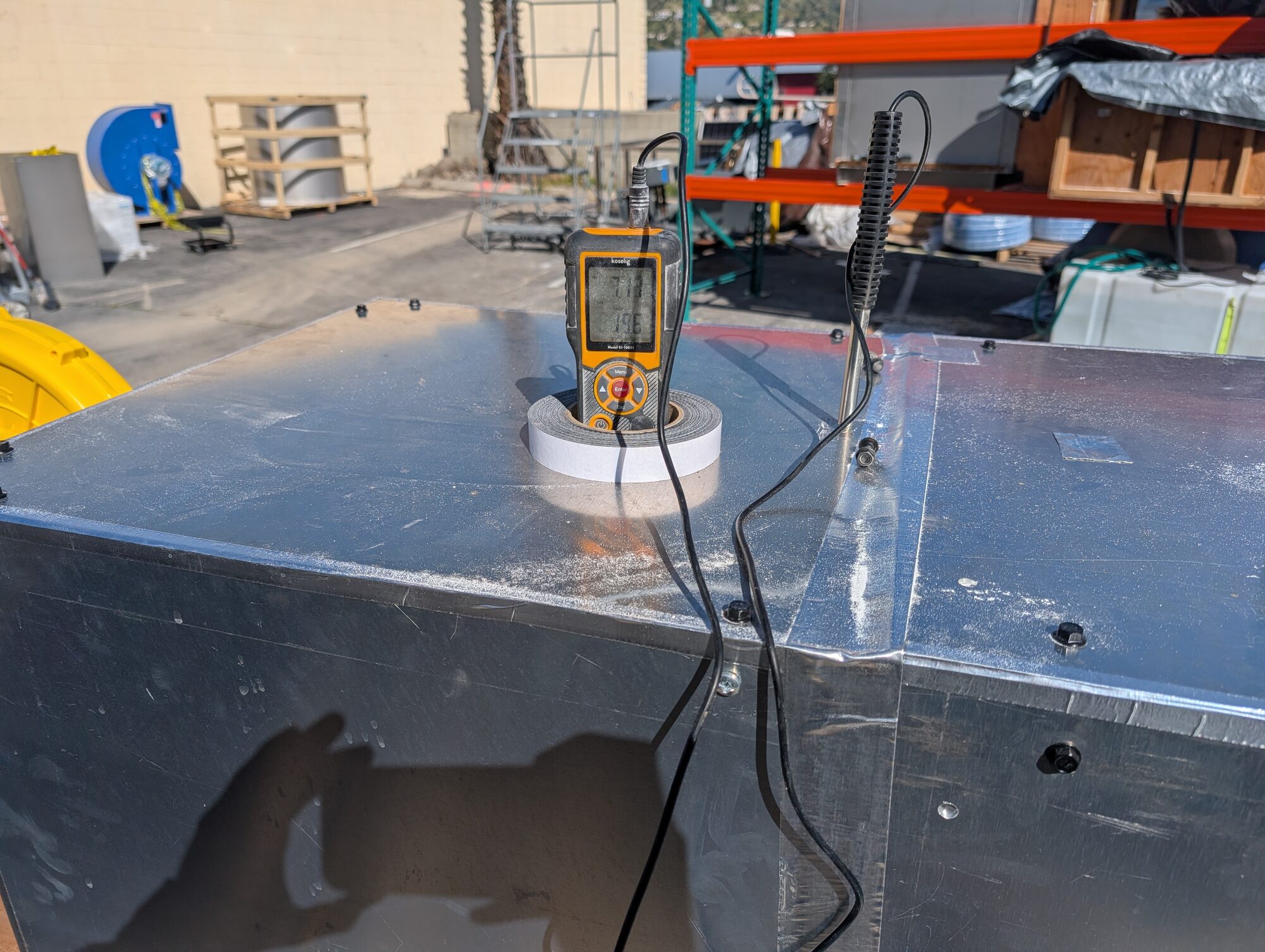
Anemometer and ΔP sensors read inside the entrainment plenum.
The wet side
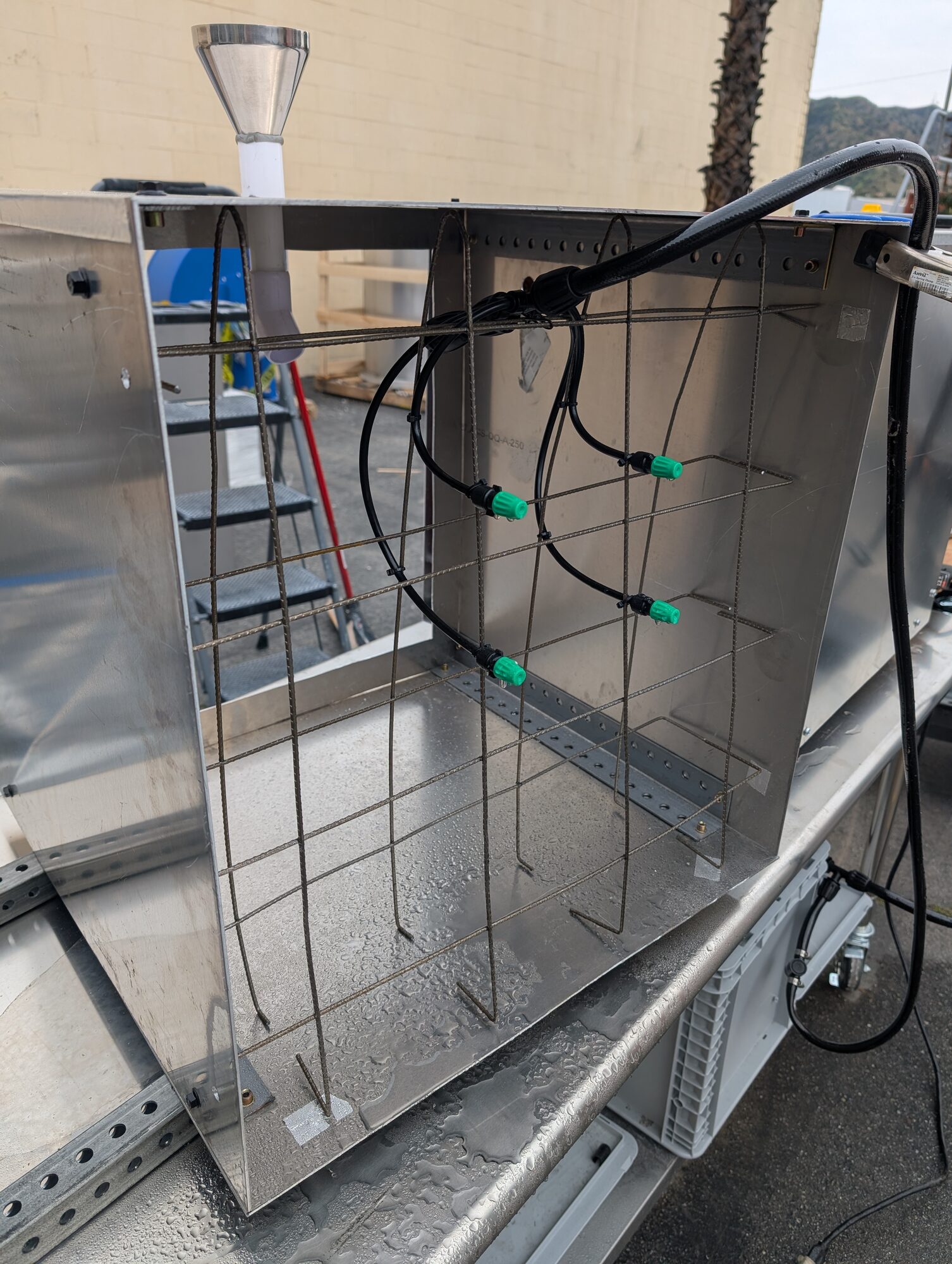
The recirculation grid. Water came up from the tote on the shelf below, wetted the media, and drained back. [?: pump and nozzle spec?]
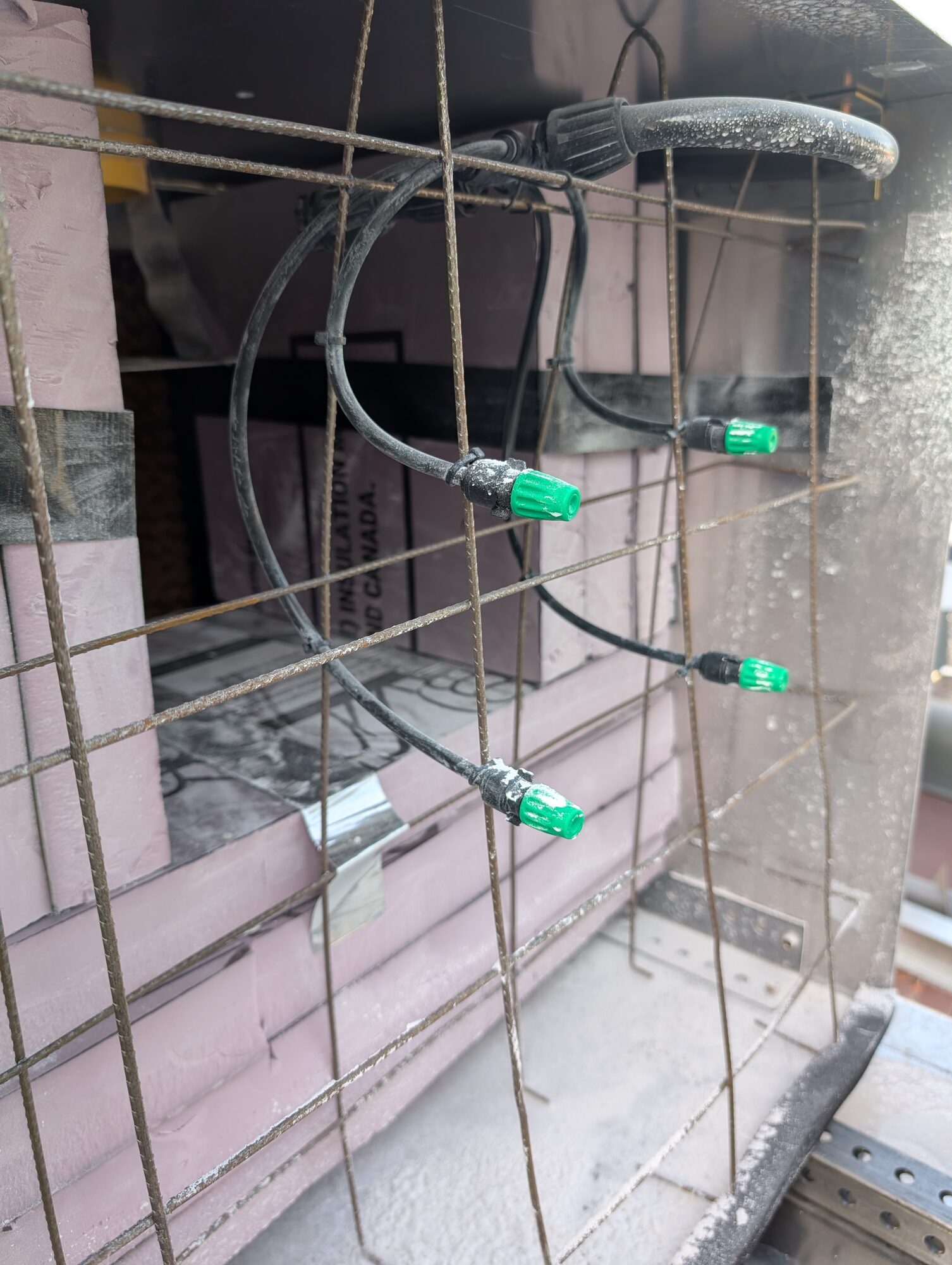
Nozzles up close, tied off to the grid so they could be repositioned between runs. The white dusting on everything is the calcium.
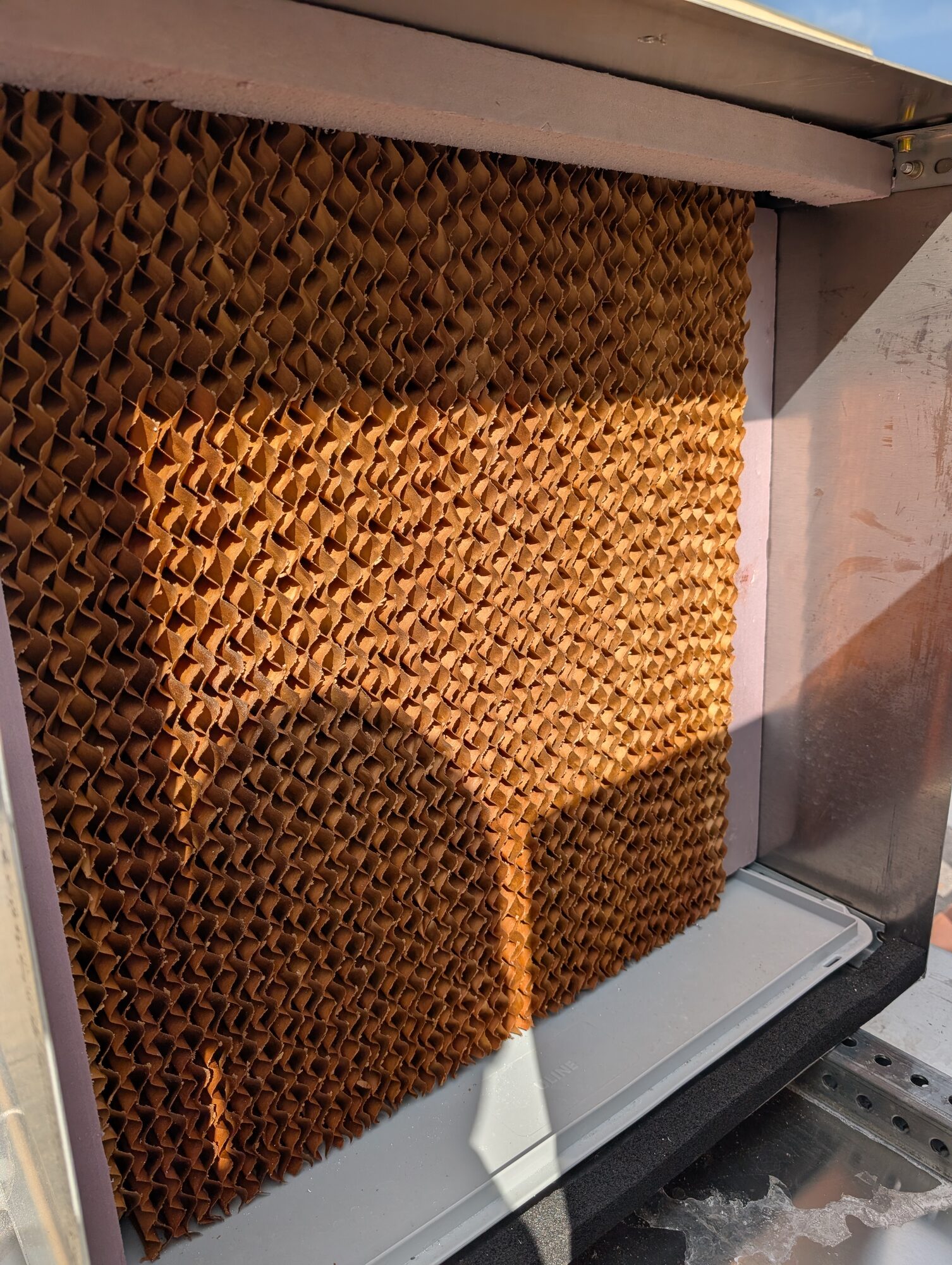
Cellulose evaporative media — this section for humidification not filtration, carbonation requires humid air.
The dry side
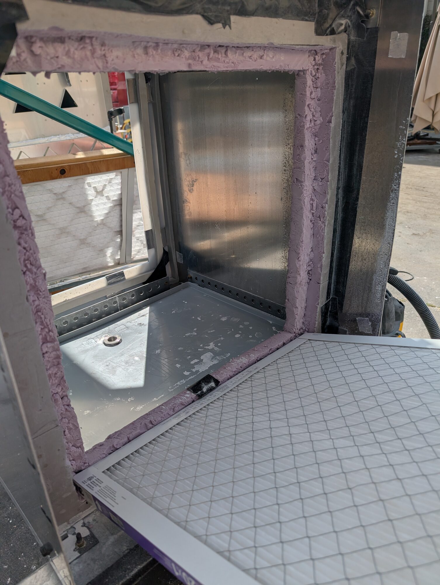
Dry media in the same frame, so both sides of the comparison saw the same duct, the same sample, and the same instrumentation. The purple sprayed foam is the gasket that makes the union seal.
An interlude, for some delicate forklifting
A test campaign is never the only thing happening. Work on the skid paused now and then for some delicate forklifting — moving prototype hardware that is large, expensive, and not especially keen on being lifted.
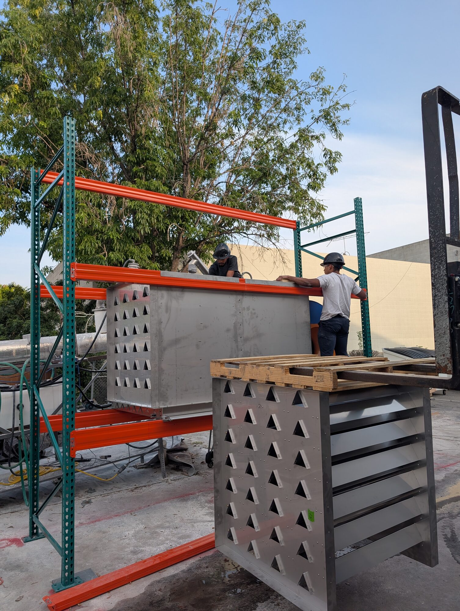
Placing a stainless assembly onto the racking. Nothing about this is fast. [?: what's being lifted here, and where was it going?]
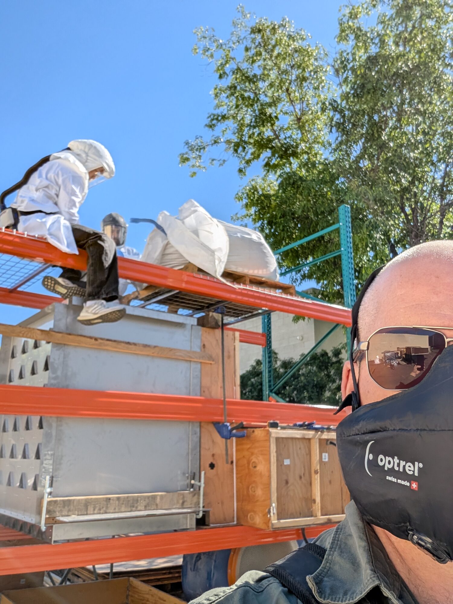
[?: what's on the racking here — sorbent? And what were the crates for?]
Results
With these solutions in place the testing was executed and data was gathered. The data showed that wet filtration was as effective as a MERV 7 filter while inducing less resistance, and most importantly, much longer maintenance cycle.
What went wrong
- The sample wouldn't stay in the air. Narrowing the airway to speed the flow helped but didn't fix it. It took the surplus sanitary gate plus the sling to get consistent entrainment.
What went right
- One skid, both configurations. The rail and the nutserted cubes meant wet and dry ran in the same duct with the same sample and the same sensors, so the comparison held up.
- Don't build what you don't need to. A wheeled steel table already in the building became the frame.
- The surplus shelf had the answer. The electronic sanitary gate was the piece that turned a fiddly manual drop into repeatable data.
- 90%+ entrainment from a sling. A late, cheap idea that made the numbers trustworthy.
- Modularity, hidden wins. Weeks later we ended up stuck because we needed a flake drying intermediate holding area, the test rig was quickly reconfigured and allowed main prototype testing to continue.
Role
I proposed the campaign, wrote the test plan, designed and built the skid, and ran the testing.
Notes
- Timeline: proposal January 2026, build January–February 2026, testing late February 2026.
- Outcome: the campaign was successful in gaining approval for the full sized prototype that could be integrated into the current carbonator build. Just in time too — I had been begging AK, lead engineer, for "just a couple more inches" so that the dry filters could be replaced with the wet filtration. I ended up 2mm shy and used a grinder to remove part of a tab for an extra snug fit.